
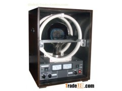


We offer e/m experiment usefull in physics and material science labs. Our arrangement for measuring e/m, the charge to mass ratio of the electron is a very simple set-up. It is based on Thomson’s method. The e/m-tube is bulb-like and contains a filament, a cathode, a grid, a pair of deflection plates and an anode. The tube is filled with helium at a very low pressure. Some of the electrons emitted by the cathode collide with helium atoms which get excited and radiate visible light. The electron beam thus leaves a visible track in the tube and all manipulations on it can be seen. The tube is placed between a pair of fixed Helmholtz coils which produce a uniform and known magnetic field. The socket of the tube can be rotated so that the electron beam is at right angles to the magnetic field. The beam is deflected in a circular path of radius r depending on the accelerating potential V, the magnetic field B and the charge to mass ratio e/m. This circular path is visible and the diameter d can be measured and e/m obtained from the relation
e/m = 8V/ B2d2
This set-up can also be used to study the electron beam deflection for different directions of the magnetic field by varying the orientation of the e/m-tube.
DEscriptION OF THE EXPERIMENTAL SET-UP
The central part of the set-up is the e/m-tube. This is energized by
- Filament current supply,
- Deflection plates voltage supply,
- Continuously variable accelerating voltage supply to the anode.
The tube is mounted on a rotatable socket and is placed between a pair of Helmholtz coils. The tube can be rotated about a vertical axis, varying the orientation of the electron beam with respect to the Helmholtz coils.This allows magnetic deflection of the beam to be demonstrated. Circular, helical or undeflected paths can be seen. The direction of the current can be changed. The magnetizing current I and the accelerating voltage V are respectively measured by an ammeter and a voltmeter mounted on the front of the panel. The diameter of the electron beam path is measured by a detachable scale mounted in front of the bulb of the tube. This scale has a slider with a hollow tube (fitted with cross wires at its both ends) to fix the line of sight while making the measurements of the beam path diameter. base of the unit contains the power supply that provides all the required potentials and the current to the Helmholtz coils. The entire apparatus is contained in a wooden case for convenient storage.
Specifications
Helmholtz coils of radii: 14 cm
Number of turns: 160 on each coil
Accelerating Voltage: 0 – 250V
Deflection plates voltage: 50V – 250V
Operating Voltage: 220V AC/ 50Hz
Typical results obtained with the above set-up for variation of the diameter of the electron beam path with the accelerating voltage for a current of 1A to the Helmholtz coils are shown in the following graph. They lead to e/m equal to 1.77x10¹¹coul / Kg.
e/m Experiment
